I got my hands on an HCM65R guitar amplifier. It's an okay amp I guess, if anything it's loud enough to rise a mob against you even if you live off in a rural area. But, something that's been bothering me and many fellow reviewers it is that it lacks distortion. For me it's usually enough for blues but some palm muted metal, like Into the void with Black Sabbath, comes out a bit soft.

As both of the volumeknobs were broken I took the amplifier apart and started thinking about a way how to get this loudly purring kitty to growl like a beast. When taking it apart I saw that the PCB is really old school with large components placed with a lot of space between them. So, hack friendly! I found out what to change and how, tried and it worked. Check the video below to hear how different it got.


As both of the volumeknobs were broken I took the amplifier apart and started thinking about a way how to get this loudly purring kitty to growl like a beast. When taking it apart I saw that the PCB is really old school with large components placed with a lot of space between them. So, hack friendly! I found out what to change and how, tried and it worked. Check the video below to hear how different it got.
Demonstration
I play some random stuff with and without the modification and I think that the difference in tone is very clear.
How to do it
This is for you who knows how to solder and de-solder components on a printed circuitboard (PCB). You know these practical things but don't want go get into all details about how this amplifier works. This is not a guide for complete beginners. If you fail the job it's possible that you will leave your amplifier in an useful state. You've thus destroyed something of value and will have to play acoustically. And playing acoustically on an electric guitar, well, lame. I suggest you to only do this if you have to repair the amp anyway, say that some potentiometer is worn out or so.
Also, it may be that the overall tone of the amp get's changed with this mod even at moderate gains. After all, sound is something very subjective and I'm not sure. I got more distortion for sure though.
Make sure that the power plug is always out and has been so for a while before touching any components.
- The amplifier is attached to the cabinet with screws from the outside. Remove these screws and the net protecting the speaker element.
- Now, lift out the amplifier. It shouldn't require that much of force. If it doesn't come out too easily, chances are that you've forgotten a screw.
- Localise the preamp, it has the text preamp written on it. Take a photo of it so you remember how everything was (before it turned into a black cloud of smoke?) and de-attach the cables attached to the PCB.
- The pre-amp should be de-attached from the chassis for this job. This is done by pulling off all the plastic knobs on the potentiometers and loosening the nuts on them and the nuts on the input- and output-jacks.
- Now you should have something that looks like this.

- What you do is that you simply localize the resistor name R55. The original value of R55 is 155kOhm. The lower the value of this resistor, the more gain and distortion. This gives you various options. You can replace R55 with a fix resistor of lower value, a piece of wire with basically zero resistance or a potentiometer enabling for adjustments.

I put a potentiometer where R55 was, but ended ut turning it down to zero anyway after playing around with it. So, probably the best and easiest thing to do here is just replacing R55 with a piece of wire. I wouldn't try different fix resistors, as soldering and de-soldering many of these could destroy the connection points at the circuit boards.
If you want to use a potentiometer, remember that a standard potentiometer has three connections, and the resistance doesn't vary between two of them. You have to connect some of the two pairs of connectors of the potentiometers were the resistance varies to the place where R55 was. Just ignore or cut off the third connector. Polarity doesn't matter. Play around with different settings on the potentiometer, with the power off, until you're happy. - Put things back together, rock n' roll :) Remember the piece of sealing "fluff" that should be between the amplifier and the cabinet.


How it works
Distortion is interesting. It's basically the act of cutting the tops of the signal you feed into the amp from the guitar. Look at the diagram below for an explanation.

A nice, smooth mathematically exact sinosoidal have it's peaks more or less brutally cut off. Seeing this diagram, a PhD in mathematics probably gives off a tear and sighs. What could previously be described by a simple formula, is now likely only best described by numerical fourier transforms on real life data. Hearing the destroyed waveform though, the very same professor might as well want to put the tie on his head, head bang and stage dive over the book shelves in the reference library. What I'm trying to get at is that it's hard to predict what will sound well and not. This abuse of waveforms is called distortion, can be absolutely awsome, and is the reason why large portions of the popular music today exists! I mean, not even Rolling Stones would be Rolling Stones without these ill-treated signals.
In this example the clipping is done using diodes. As you may know, diodes don't conduct any current until there is a certain voltage drop over them. As the way this circuit is set up, the signal will "flatten out" when the voltage it's fed with is higher than the diodes voltage forward drop, see the figure below.

It should be noted though that this is a bit simplified, and assumes non-zero impedance in series with the diode. Also, most diodes don't clip this hard. But the principle remains the same.
What the mastervolume does is that it just amplifies the already distorted signal, without adding more distortion itself (well, not before you play loud enough to you go deaf, anyway).
Overdrive using hex-inverters
Logical inverters can be self-biased and used as linear amplifiers. When they are cranked up enough, they start to clip. The HCM65R uses various of these connected in series. See the excerpt from the HCM65R schematics below.

HCM65R Schematics
There are many ways in which this circuit could be modified to get more distortion. The key factor I was looking for was how to introduce more gain somehow. More gain should create more linear clipping, as previously explained. This could have been done before the node to the left marked LN1, but that would have affected the clean channel which I didn't want.
Link to an inverter data sheet
It can be seen that the gain Au is determined by a ration between R1 and R2, and for it to be as high as possible R1 should actually be zero. Bingo! If then any of the resisors R55, R35 etc in the amp were made smaller, there should be more gain and then more distortion. As the ratio between R55 and R24 is the one that can be changed the most changing only one component I choose to replace R55 with a variable resistance.
Also, I'm not sure how modifying the other three inverters would affect the tone, for one as the last one is hooked up as a low-pass filter. A model for how the the circuit would affect signal can be derived quiet easily, but a model for how this signal would sound when cranking out a power chord is well let's say behind the scope of this article :) Changing R55 for a smaller value felt safer as that should be the same as just adding a possibly clipping pre-amp to the guitar. However, the drawback is that if this first inverter starts clipping, it's before the "distortion" knob on the pre-amp. That means that there is a risk that there will always be distortion in the tone when the amplifier is in overdrive mode, if not the volume knob on the guitar is turned down. This leads to a worse signal-to-noise-ration and well... The mod is a compromise.
In this example the clipping is done using diodes. As you may know, diodes don't conduct any current until there is a certain voltage drop over them. As the way this circuit is set up, the signal will "flatten out" when the voltage it's fed with is higher than the diodes voltage forward drop, see the figure below.

It should be noted though that this is a bit simplified, and assumes non-zero impedance in series with the diode. Also, most diodes don't clip this hard. But the principle remains the same.
No gain, no...
Most guitar amplifiers have at least two sections, one marked pre-amp something and one marked master volume something. The thing is that the pre-amp is usually in series with the circuit creating distortion, like the diode below. What the pre-amp does is that it amplifies the signal, making a larger proportion of the signal getting clipped. That is heard as more distortion. After studying the schematics for the HCM65R for a while, I couldn't find where this diode responsible for the rock n' roll would be located.What the mastervolume does is that it just amplifies the already distorted signal, without adding more distortion itself (well, not before you play loud enough to you go deaf, anyway).
An analog circuit using digital components
It turns out, the HCM65R uses overdriven logical inverters to seal the deal! I found this great page that explains how it works:Overdrive using hex-inverters
Logical inverters can be self-biased and used as linear amplifiers. When they are cranked up enough, they start to clip. The HCM65R uses various of these connected in series. See the excerpt from the HCM65R schematics below.

HCM65R Schematics
There are many ways in which this circuit could be modified to get more distortion. The key factor I was looking for was how to introduce more gain somehow. More gain should create more linear clipping, as previously explained. This could have been done before the node to the left marked LN1, but that would have affected the clean channel which I didn't want.
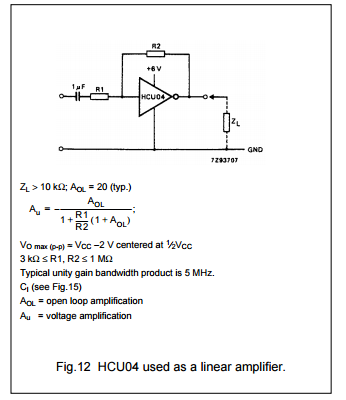
Some math behind it
In a datasheet from NXP I foundan expression for the gain of a HEX inverter when used as a linear amplifier, it can be seen below.Link to an inverter data sheet
It can be seen that the gain Au is determined by a ration between R1 and R2, and for it to be as high as possible R1 should actually be zero. Bingo! If then any of the resisors R55, R35 etc in the amp were made smaller, there should be more gain and then more distortion. As the ratio between R55 and R24 is the one that can be changed the most changing only one component I choose to replace R55 with a variable resistance.
Also, I'm not sure how modifying the other three inverters would affect the tone, for one as the last one is hooked up as a low-pass filter. A model for how the the circuit would affect signal can be derived quiet easily, but a model for how this signal would sound when cranking out a power chord is well let's say behind the scope of this article :) Changing R55 for a smaller value felt safer as that should be the same as just adding a possibly clipping pre-amp to the guitar. However, the drawback is that if this first inverter starts clipping, it's before the "distortion" knob on the pre-amp. That means that there is a risk that there will always be distortion in the tone when the amplifier is in overdrive mode, if not the volume knob on the guitar is turned down. This leads to a worse signal-to-noise-ration and well... The mod is a compromise.
Kommentarer
Skicka en kommentar